Did you know that ATC conversations and conversations between planes are freely available, with no encryption? It is legal to listen in on ATC conversations, and in this guide I will tell you how if you have some free time.
What You Need
RTL-SDR Stick and Antenna (x1)
This is the antenna and radio processor we will be using to get a signal from an air traffic control tower.
If it is your first time using SDR# (SDRSharp), then you must install SDR#, then install the drivers. The below guide will show you how to do so.
First, install SDR# and let the installation wizard guide you through the process.
Then, open the newly added program Zadig and you should see a screen like the one below.
A: This is where you choose the interface you want to install drivers for
B: This is where you check if a driver was installed
C: This is where you can install the drivers
Follow the steps below:
First, use dropdown A to select an interface. The interface must start with Bulk-in, Interface. If you have multiple bulk-in interfaces, repeat these steps for every one
Next, make sure textbox B tells you that there is no driver installed
Finally, click Install WCID Driver (button C)
Opening SDR#
Once all the drivers are installed, you may close out of Zadig and open SDR#. You should see a screen like the one below.
A: This is the frequency selector. This is where you can choose which frequency your antenna is supposed to be tuned to. Right now it is tuned to 120 MHz, but in the next section you will learn to find the frequency of your ATC tower
B: This is where you can choose your radio settings. For this tutorial, keep the default settings but change the radio mode to AM
C: This is where you choose the source of the radio stream. Right now you want it set to RTL-SDR USB
D: This is where you can visualize the radio waves. You can click anywhere on this to set the frequency to the location of the waves to which you clicked. You can drag the lighter waves to set the bandwidth. You want to make sure that the bandwidth is not too big otherwise you will get interference, but not too small so you only get part of the wave. I have set my bandwidth to 7.557 kHz
Reading Aerospace Vector Maps
Using a site, like SkyVector, you can find your airport and look at the frequency under it. Tune to that frequency. For place value context, think of the second segment of numbers as MHz SkyVector shows frequencies in megahertz.
Some airports, like the ones marked with a star, do not have full-time ATC, meaning that planes have to talk directly to each other.
Tune to this frequency on SDR#.
Listening to these frequencies
Look for any spikes in these frequencies. Ste the frequency to the frequency of these spikes (you can do this easily by clicking on these spikes) Adjust the bandwidth to these spikes, hovering over the top-right Zoom button and using the slider below it to zoom into the waves. Click on the top-left gear icon and adjust the setting to match the ones below:
Now, turn the volume up and listen. If you do not hear talking, experiment with the bandwidth or choose another frequency. A good frequency should be like the one below:
Done!
And that is the end of the project! Pretty easy, right? There are some caveats, though. You will only get the best signal when you live no further than 50 kilometers away from an airport with a full-time ATC, and the radio tends to disconnect a lot if not screwed in fully. Either way, it is still a super cool project, and is definitely worth trying out if you are interested in this kind of thing. Frequencies might not be exact, so experiment a little!
Before we start this project, you need to know a little bit about GPS. Satellites will send signals on their distance from the module. Once four or more satellites are connected and giving out this data, the receiver can then use the data to figure out the exact location of the user.
The receiver will then present this data in the form of NMEA sentences. This is a standard communication developed by the National Marine Electronics Association. We will be using TinyGPS++ to parse these.
Using the GPS with Arduino
For this part, you don’t need the LCD. This will show you how to log the GPS output to the serial monitor. We will then parse this data using TinyGPS++.
Preparations
First, open Arduino IDE and you will be greeted with a blank sketch.
At the top toolbar, click Ctrl + Shift + I to bring up the library manager and type “TinyGPSPlus” and install the top result.
Now that we are all prepared, lets start writing the code. First, we include the library that helps us communicate with the GPS.
#include <SoftwareSerial.h>
Next, we include the library that parses NMEA sentences.
#include <TinyGPSPlus.h>
Now, declare the communication between the Arduino and the GPS and then the parser.
SoftwareSerial ss(4,3);
TinyGPSPlus gps;
After that, we go inside the void setup() function and we initiate the communication between the computer and the Arduino and the GPS and Arduino.
Serial.begin(9600);
ss.begin(9600);
Next, we go into void loop() and specify that whatever is below this line of code should only happen when the Arduino receives a signal.
while (ss.available() > 0)
Then, we encode the data in a format that the GPS can then parse.
gps.encode(ss.read());
Then, we create an if block so the serial monitor only displays our data when the data the GPS is outputting is valid.
if (gps.location.isUpdated()) {

}
Now, inside the if block, we can access all the data and print it to the serial monitor.
Serial.print("Latitude= ");
Serial.print(gps.location.lat(), 6); //6 for 6 decimal places
Serial.print("Longitude= ");
Serial.print(gps.location.lng(), 6); //6 for 6 decimal places
Your full code should look like this:
#include <SoftwareSerial.h>
#include <TinyGPSPlus.h>

SoftwareSerial ss(4,3);
TinyGPSPlus gps;

void setup() {
  // put your setup code here, to run once:
  Serial.begin(9600);
  ss.begin(9600);
}

void loop() {
  // put your main code here, to run repeatedly:
  while (ss.available() > 0)
  gps.encode(ss.read());

  if (gps.location.isUpdated()) {
    Serial.print("Latitude= ");
    Serial.print(gps.location.lat(), 6); //6 for 6 decimal places
    Serial.print("Longitude= ");
    Serial.print(gps.location.lng(), 6); //6 for 6 decimal places
  }
}
Wiring
The wiring is shown below:
GPS RX > Digital 4 on Arduino
GPS TX > Digital 3 on Arduino
GPS VCC > Power 3.3V on Arduino
GPS GND > Power GND on Arduino
Uploading
Now, with the Arduino IDE opened and the code ready, press Ctrl + U on your keyboard. The code will write and start outputting to the serial monitor, which you can access by pressing Ctrl + Shift + M on your keyboard or by going to the top toolbar and clicking Tools > Serial Monitor. The GPS will take a couple minutes to get its location. You may want to stick the antenna outside for this, as it will take a long time to get its location indoors.
Soon, you will be able to view the data coming in.
There is a common WiFi attack that can disconnect any device on the network you are currently on. It also works on networks that you are not currently on.
How it works
There is a protocol in WPA2 that lets you disconnect a device safely from a network. However, these packets are not encrypted, so anyone with a WiFi-enabled device (like the ESP8266) can fake these packets.
Installing the software
First, go to the ESP8266 deauther page and download the latest release and download the file esp8266_deauther_[VERSION]_NODEMCU.bin.
Next, download the ESP8266 Flasher and run the utility. Flash the binary file (the .bin you downloaded) at 0x00000. Click Flash and wait till it completes.
Running attacks
On a device, connect to the Wi-Fi network named pwned and enter the password deauther. Next, go to the IP address 192.168.4.1 and click I have read and understood the risks and choose a target network. Under the Attacks tab, begin the attack Deauth.
A note on WPA3
WPA3, which was passed as an official WiFi protocol, encrypts these packets so hackers cannot abuse them. However, some WiFi routers still use WPA2, so this attack will still work sometimes.
In this post, I will be showing you how to start feeding flight data to three services: Flightradar24, ADS-B Exchange, and FlightAware. This post may be helpful to some of you who want to run your own flight feeder, and can’t tell which is a better service to feed to.
The main benefit of running your own Raspberry Pi flight tracker is that you will get paid accounts for free. For example, you will get a free FlightAware enterprise account, a subscription valued at around $89.95 a month. FlightRadar24 will also give you a free business plan, which costs $49.99 a month. If you also want to support non-proprietary websites, you can also give flight data to ADS-B Exchange.
What you will need (hardware)
Below are the parts you will need:
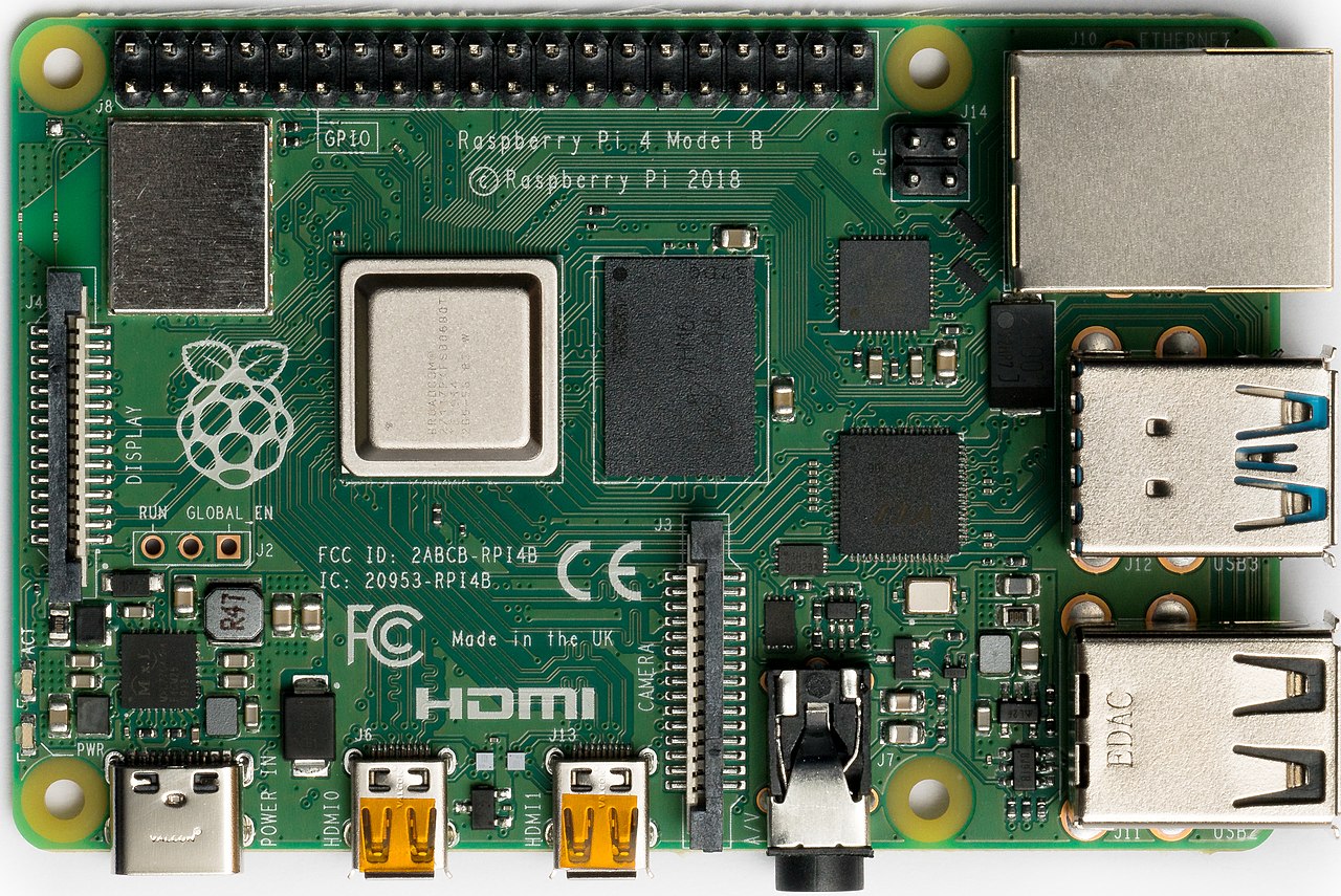
Raspberry Pi 3B (x1, required)
The Raspberry Pi will be our microcontroller (This also works with other models, just not the Zero or the Pico; you can see FlightAware’s compatibility list here)
To begin the installation, we will have to first start feeding to FlightAware. To begin, first, create an account at their website, or log in at their website.
Note that you must select the correct drive, as this will erase your drive.
Configuring the ISO
If you want to enable SSH on your PiAware, or you have a wireless network configuration that you want to set (this will be typically everyone, unless you are using an ethernet cable on your Raspberry Pi), you must follow the below steps to configure the new operating system to use your configurations. You can refer to the configurations at FlightAware’s Website, or you could not set a default configuration, and once the PiAware has booted up, configure it using Bluetooth.
Booting it up
Now, you can put it all together! Connect your ADS-B antenna to your Raspberry Pi via USB, and then put the SD card through the back. Then, plug in the HDMI cable (and ethernet if you are going to be using it), and power it on.
Now, once the Raspberry Pi has booted up, you should see a screen showing the PiAware Status. If you did this correctly, it should be connected. You will also need to connect a keyboard if you do not know your PiAware’s IP address. If it asks you for credentials, the default is pi for username, and raspberry for password.
Setting up the FlightAware feeder
Now we get to the fun part! Now, we set up the feeders. Let’s start off with the FlightAware feeder. Since we flashed the custom ISO file, FlightAware is going to be installed, just not set linked to an account. Create a basic plan FlightAware account at their website if you don’t already have one, and claim your PiAware. Once that is set up, make sure you are connected to the same network as your PiAware. It will come in handy for later. Once you do that, make sure you are still on the status page on your PiAware, click Alt+F2 (or whatever key it says to press to open the terminal and run commands). If it asks you for credentials, the default is pi for username, and raspberry for the password (unless it is set otherwise, of course). Now run the following command:
BASH

hostname -I
This should return your Pi’s IP address. Now, on another device, navigate to your IP address on the SkyAware page. For example, if my Pi’s IP address is 192.168.1.1, I will navigate to the following website:
URL

http://192.168.1.1/skyaware
After that, you should see a map with all the aircraft you are tracking. You have successfully set up FlightAware! After some time, your basic account will be upgraded, and you can view your ADS-B statistics.
Setting up FlightRadar24
Now, open the terminal and run the following command:
You will then be asked some questions about antenna position, fr24 sharing key, and other things.
Now, we need to configure FlightRadar24. To begin, sign up for an account at their official website. Note that all you need to do is sign up for a free account and do not select any paid plans. This is because your account will automatically be upgraded at the end of this tutorial.
Run the following command to enter configuration:
BASH

sudo fr24feed --signup
You will be asked questions about you and the antenna that you are using. Answer the questions similar to the ones below:
Email Address: Enter the same email address you used to sign up for FlightRadar24. This is the same email address that your sharing key will be sent to, and the same email address that your account on will be upgraded.
FR24 Sharing key: If you have never set up a feeder or have never got a sharing key from FlightRadar24, leave this blank. If not, enter your FlightRadar24 sharing key.
Participating in MLAT Calculations: Answer yes, unless you know you don’t want it or need it.
Autoconfiguration for dump1090 (if asked): Yes
Latitude & Longitude: Use a website like latlong.net to find your latitude and longitude. It is best to be as accurate as possible. Enter this question in the form of XX.XXXX and XX.XXXX (leave out any extra numbers).
Altitude: This is your altitude from sea level. You can use whatismyelevation.com to find your altitude.
Receiver Selection: If you are using a DVB-T (the type I put in the parts list) stick then I strongly recommend option 1. If you encounter an error regarding dump1090 in this tutorial, restart the tutorial and click option 4. If you do not have a DVB-T stick, check out your other options.
Dump1090 Arguments (if asked): Leave this blank and hit enter.
Raw Data Feed: No, unless you know what you are doing.
Basestation Data feed: No unless you know what you are doing.
Logfile Mode: 48-hour, 24 rotation.
Logfile Path: This will be the path that the log file is saved to. If you want to use a custom path for logs, put it here. If not, stick with the default and hit enter.
FlightRadar24’s configuration should return that everything is correctly set up. The program should also give you a sharing key. Save this key as you may need it later in the future.
To begin feeding ADS-B data to FlightRadar24, enter the command below. Note that MLAT or general feeding might take some time to show up. For me, it took 30 minutes before the feeder was actively sending data to FlightRadar24:
BASH

sudo systemctl restart fr24feed
You can go to the data page and view your feeder statistics. If you want to access the web UI for FlightRadar24, then go to your Raspberry Pi’s IP address (remember, you can access it with sudo hostname -I), and access it via a web browser on port 8754, unless set otherwise. For example, my Raspberry Pi’s IP address is 192.168.1.252, so I access it by using http://192.168.1.252:8754.
Also, it is important to note that it may take some time for the receiver to start working and sending data. For me, it took 30 minutes before flight data was sent to the services I was feeding to.
Setting up MLAT for FlightAware
If you want to set up MLAT configurations on FlightAware (we highly recommend doing so, it can increase the amount of positions seen), then follow our steps.
First, go to your FlightAware data sharing page and clcik the gear icon next to the nearest airport, labeled in orange.
Then, enable MLAT and Mode S Alliteration. Put in the same details as you did for FlightRadar24, or new details if you have to.
Setting up ADS-B Exchange
First, we need to download ADS-B Exchange. You can do that with the following command:
You will be asked a couple questions. For the first one, type in a random username, but note that this username will be public. Next, enter the details it asks for, and it will begin configuring. Note that this may take a while.
The script should output a sharing key. You can use this to view your feeder statistics at the official website of ADS-B Exchange. You should also be able to access your web interface on the adsbx page. This will be your Raspberry Pi’s IP address, with /adsbx at the end. For me, the URL was http://192.168.1.252/adsbx.
In this guide, I will be turning a Raspberry Pi into an OpenWrt router. This is good for travel, and it can connect to VPN servers to give you secure VPN internet.
First, we need to install OpenWrt on the board. To do that, put the MicroSD card into the MicroSD card reader, then plug the MicroSD card reader into the computer.
Once that is done, download the proper firmware from this site. Then, once you have the Raspberry Pi Imager open, select, click “Choose OS”. Then scroll down and click “Use Custom”, then select the location of the firmware that you downloaded from the OpenWrt Wiki.
Click “Select Drive”, then click the drive of the SD card reader.
Step 2: Connect to OpenWrt via SSH
Now, plug the ethernet cable into your Raspberry Pi, then plug the other end into your computer. Open Command Prompt, then run:
BATCH

ssh root@192.168.1.1
On the fingerprint prompt, type “yes”.
Step 3: Setting a password
When we used SSH to log in to the OpenWrt session, notice that it did not prompt us for a password. Super insecure. To set one, run the command. This is also how you change the password on any Linux device:
Run these commands. I hooked mine up to the LAN interface, if you want to use Wi-Fi, follow the official documentation. These will configure OpenWrt to connect to your network.
ASH SHELL

uci set network.lan.ipaddr=192.168.2.2
uci set network.lan.gateway=192.168.2.1
uci set network.lan.dns=192.168.2.1

uci commit
service network restart
Step 6: Partitioning
Create a partition to store data. We will install fdisk and use it:
opkg update
opkg install fdisk
fdisk /dev/mmcblk0
To create two partitions (one for /home and one for /srv), use the following fdisk commands.
p to print the current partition table.
n then e to create an extended partition.
n then l to create the first partition. When asked for the last sector, type +2G to make it 2GB large.
n then l to create the second partition. When asked for the last sector, leave empty to fill the remaining space.
Now we can mount the first partition at /home and the second at /srv. Both are on a flash SD card, the noatime flag is important.
ASH SHELL

opkg update
opkg install block-mount
block detect | uci import fstab
uci set fstab.@mount[2].target=/home
uci set fstab.@mount[2].enabled=1
uci set fstab.@mount[2].options=noatime
uci set fstab.@mount[3].target=/srv
uci set fstab.@mount[3].enabled=1
uci set fstab.@mount[3].options=noatime
uci commit
Create the srv mount point, as the other one already exists.
ASH SHELL

mkdir -p /srv
Mount both partitions.
ASH SHELL

block mount
Step 8: Set the hostname
ASH SHELL

uci set system.@system[0].hostname='thetechmaker-good.hi.testing'
uci commit
Step 9: Remove unused packages
OpenWrt was originally a Linux distribution for routers, so it might come with useless networking software you’ve never heard of. You can remove this with the following commands:
By this time, you’d probably want a temperature sensor in the house – one less than $25. If you have one, you are probably wanting a better one. Here is an easy solution to this problem.
Once you have got that down go to Tools > Script Editor. We’ll continue from there.
In the script editor, copy and paste the code given here. Edit the script ID in the code. The script ID is found in the place where “vbn” is in the given URL:
Now go to Publish > Deploy as a web app. The “Project version” will be “New”. Select “your email id” in the “Execute the app as” field. Choose “Anyone, even anonymous” in the “Who has access to the app” field. And then click on “Deploy”. Note that When republishing please select the latest version and then Deploy again. Type “NewScriptCreated” in the “ProjectVersion” field.
You will have to give Google permission to deploy it as a web app. Just click on “Review Permissions”. Then choose your Email ID here using which you have created the spreadsheet.
Click on “Advanced”.
And then click on “Go to ‘your_script_name‘(unsafe)“. Here in my case, it is “TempLog_Script”.
Click on “Allow” and this will give permission to deploy it as a web app.
Now you can see the new screen with a given link and named “Current web app URL”. This URL contains Google Script ID. Just copy the URL and save it somewhere.
Testing the DHT11/22
Use the given circuit diagram and code:
Diagram:
Code:
C#, C++, C

#include "DHT.h"

#define dht_apin A0

DHT dht;

#define DHTTYPE DHT22 //Change this to any type of DHT Sensor you're Using!

DHT(dht_apin, DHTTYPE);

void setup() {

// put your setup code here, to run once:

Serial.begin(9600); //Starts serial

delay(5000); //Waits before reading from sensor

Serial.println("DHT22 Temp. And Humi. Test"); //Prints the intro

}

void loop() {

// put your main code here, to run repeatedly:

dht.read11(dht_apin); //Reads from the sensor

Serial.println("Humi. ---------- "); //Prints humidity

Serial.print(DHT.humidity); //Prints humidity

Serial.print("% "); //Marks the humidity as %

Serial.print("Temp. ------------ "); //Prints temperature

Serial.print(DHT.temperature); //Prints temperature

Serial.print("℃") //Marks the temperature unit

delay(2000); //Waits 2 seconds before doing the loop again fastest is once evrey 2 seconds

} //end loop
It should be printing the temperature and humidity. If it is not, try running this code at rate 9600 that will print “Hello!” every second to see if you are getting any serial communication at all:
C#, C++, C

#define one_second 1000

#define the_word_hello "Hello!"

void setup() {

// put your setup code here, to run once:

Serial.begin(9600);

delay(5000);

}

void loop() {

// put your main code here, to run repeatedly:

Serial.print(the_word_hello);

delay(one_second);

}
Programming language(s) C#, C++, C: ***{Code starts after this line}***

#include <ESP8266WiFi.h>
#include "HTTPSRedirect.h"
#include "DebugMacros.h"
#include <DHT.h>

#define DHTPIN D4                                                           // what digital pin we're connected to
#define DHTTYPE DHT11                                                       // select dht type as DHT 11 or DHT22
DHT dht(DHTPIN, DHTTYPE);

float h;
float t;
String sheetHumid = "";
String sheetTemp = "";

const char* ssid = "";                //replace with our wifi ssid
const char* password = "";         //replace with your wifi password

const char* host = "script.google.com";
const char *GScriptId = "AKfycbxy9wAZKoPIpPq5AvqYTFFn5kkqK_-avacf2NU_w7ycoEtlkuNt"; // Replace with your own google script id
const int httpsPort = 443; //the https port is same

// echo | openssl s_client -connect script.google.com:443 |& openssl x509 -fingerprint -noout
const char* fingerprint = "";

//const uint8_t fingerprint[20] = {};

String url = String("/macros/s/") + GScriptId + "/exec?value=Temperature";  // Write Teperature to Google Spreadsheet at cell A1
// Fetch Google Calendar events for 1 week ahead
String url2 = String("/macros/s/") + GScriptId + "/exec?cal";  // Write to Cell A continuosly

//replace with sheet name not with spreadsheet file name taken from google
String payload_base =  "{\"command\": \"appendRow\", \
                    \"sheet_name\": \"TempSheet\", \
                       \"values\": ";
String payload = "";

HTTPSRedirect* client = nullptr;

// used to store the values of free stack and heap before the HTTPSRedirect object is instantiated
// so that they can be written to Google sheets upon instantiation

void setup() {
  delay(1000);
  Serial.begin(115200);
  dht.begin();     //initialise DHT11

  Serial.println();
  Serial.print("Connecting to wifi: ");
  Serial.println(ssid);

  WiFi.begin(ssid, password);
  while (WiFi.status() != WL_CONNECTED) {
    delay(500);
    Serial.print(".");
  }
  Serial.println("");
  Serial.println("WiFi connected");
  Serial.println("IP address: ");
  Serial.println(WiFi.localIP());

  // Use HTTPSRedirect class to create a new TLS connection
  client = new HTTPSRedirect(httpsPort);
  client->setInsecure();
  client->setPrintResponseBody(true);
  client->setContentTypeHeader("application/json");
  Serial.print("Connecting to ");
  Serial.println(host);          //try to connect with "script.google.com"

  // Try to connect for a maximum of 5 times then exit
  bool flag = false;
  for (int i = 0; i < 5; i++) {
    int retval = client->connect(host, httpsPort);
    if (retval == 1) {
      flag = true;
      break;
    }
    else
      Serial.println("Connection failed. Retrying...");
  }

  if (!flag) {
    Serial.print("Could not connect to server: ");
    Serial.println(host);
    Serial.println("Exiting...");
    return;
  }
// Finish setup() function in 1s since it will fire watchdog timer and will reset the chip.
//So avoid too many requests in setup()

  Serial.println("\nWrite into cell 'A1'");
  Serial.println("------>");
  // fetch spreadsheet data
  client->GET(url, host);

  Serial.println("\nGET: Fetch Google Calendar Data:");
  Serial.println("------>");
  // fetch spreadsheet data
  client->GET(url2, host);

 Serial.println("\nStart Sending Sensor Data to Google Spreadsheet");


  // delete HTTPSRedirect object
  delete client;
  client = nullptr;
}

void loop() {

  h = dht.readHumidity();                                              // Reading temperature or humidity takes about 250 milliseconds!
  t = dht.readTemperature();                                           // Read temperature as Celsius (the default)
  if (isnan(h) || isnan(t)) {                                                // Check if any reads failed and exit early (to try again).
    Serial.println(F("Failed to read from DHT sensor!"));
    return;
  }
  Serial.print("Humidity: ");  Serial.print(h);
  sheetHumid = String(h) + String("%");                                         //convert integer humidity to string humidity
  Serial.print("%  Temperature: ");  Serial.print(t);  Serial.println("°C ");
  sheetTemp = String(t) + String("°C");

  static int error_count = 0;
  static int connect_count = 0;
  const unsigned int MAX_CONNECT = 20;
  static bool flag = false;

  payload = payload_base + "\"" + sheetTemp + "," + sheetHumid + "\"}";

  if (!flag) {
    client = new HTTPSRedirect(httpsPort);
    client->setInsecure();
    flag = true;
    client->setPrintResponseBody(true);
    client->setContentTypeHeader("application/json");
  }

  if (client != nullptr) {
    if (!client->connected()) {
      client->connect(host, httpsPort);
      client->POST(url2, host, payload, false);
      Serial.print("Sent : ");  Serial.println("Temp and Humid");
    }
  }
  else {
    DPRINTLN("Error creating client object!");
    error_count = 5;
  }

  if (connect_count > MAX_CONNECT) {
    connect_count = 0;
    flag = false;
    delete client;
    return;
  }

//  Serial.println("GET Data from cell 'A1':");
//  if (client->GET(url3, host)) {
//    ++connect_count;
//  }
//  else {
//    ++error_count;
//    DPRINT("Error-count while connecting: ");
//    DPRINTLN(error_count);
//  }

  Serial.println("POST or SEND Sensor data to Google Spreadsheet:");
  if (client->POST(url2, host, payload)) {
    ;
  }
  else {
    ++error_count;
    DPRINT("Error-count while connecting: ");
    DPRINTLN(error_count);
  }

  if (error_count > 3) {
    Serial.println("Halting processor...");
    delete client;
    client = nullptr;
    Serial.printf("Final free heap: %u\n", ESP.getFreeHeap());
    Serial.printf("Final stack: %u\n", ESP.getFreeContStack());
    Serial.flush();
    ESP.deepSleep(0);
  }

  delay(3000);    // keep delay of minimum 2 seconds as dht allow reading after 2 seconds interval and also for google sheet
}
2: Put everything else you unboxed in the box. Close the box. Take the motherboard out of its bag and put it on top of the box:
CPU
1: Unbox the CPU. Make sure to only hold it by the edges. Never the bottom or top.
2: (carefully) Put the CPU in a static-safe spot.
3: Release the motherboard retention plate by pushing the metal stick down, out, release:
4: Now align the gold triangle on the CPU with the triangle cutout/dot cutout on the motherboard.
5: Gently place the CPU in the socket. Don’t push it or apply any force. Just drop it in.
6: Lower the retention bracket, making sure it’s guided by the top screw.
7: Lower the metal stick and put it back in. It’s okay to feel some resistance.
RAM
1: Look for 2 slots that are different colors or a diagram that shows which sticks of RAM to put in first. Pull back the right tabs of these. The left tab, on modern motherboards, does not pull back:
2: Unbox your RAM. Line the notches up:
3: Once the notch(es) are aligned, push the RAM in with even pressure on both ends until you hear a click on each end. Repeat for other sticks:
SSD
Skip if you are not installing.
1: Identify the notch similar to how you did with the RAM and insert:
2: Insert the mounting post and screw:
Cpu Cooler
Now I’m sorry, I cannot make an instruction specific to this. Resort to your cooler’s manual to find out:
PSU
1: Insert your PSU and screw:
Motherboard wire-up
1: Take out the biggest cable from the pack (let aside the power cable) and attach it to the 24-pin input on your motherboard:
2: Attach other end to a input labeld Motherboard or Mainboard:
CPU/EMS wire-up
1: Locate an 8-pin connector that is usually on the top-left closest to your CPU socket on your motherboard.
2: Connect the other end to an input labeled CPU or EMS.
3: Wire up if a second connector is present.
Cable Managment
This is really to your preference. I like to make it go around and stay away from fans and RGB. You will need zip ties:
Chasis-Mounted Functions
I’m sorry, I cannot make a guide specific to this either. Refer to the motherboard and chassis manual.
POWER IT UP
Plug in the power and switch the on/off switch to the on position. Put your case back together, plug in the keyboard, mouse, display, whatever it takes. Switch your monitor on.
Now, take a deep breath and press the power button.
TEST
You should see your motherboard’s logo.
If you see something like:
BIOS Self-Test Output

ASUS TUF Gaming Model Z390-PLUS SELF TEST
VGA Detected
Mouse Detected
Graphics Detected
Fast Boot Off

New CPU Detected! Configure it in Setup
Press F2 or DEL to enter SETUP
Go to Create Installation media > Next > **ADJUST SETTINGS TO MATCH** > Next > **PLUG IN A FLASH DRIVE THAT IS AT LEAST 8GB** > USB Flash Drive > Next > **SELECT YOUR DRIVE** > Next
Once it’s done, unplug your drive and plug it into your new PC.
Reboot the PC and follow the steps to install Windows. You can say that you don’t have a license key, but you’re going to have to activate it later.
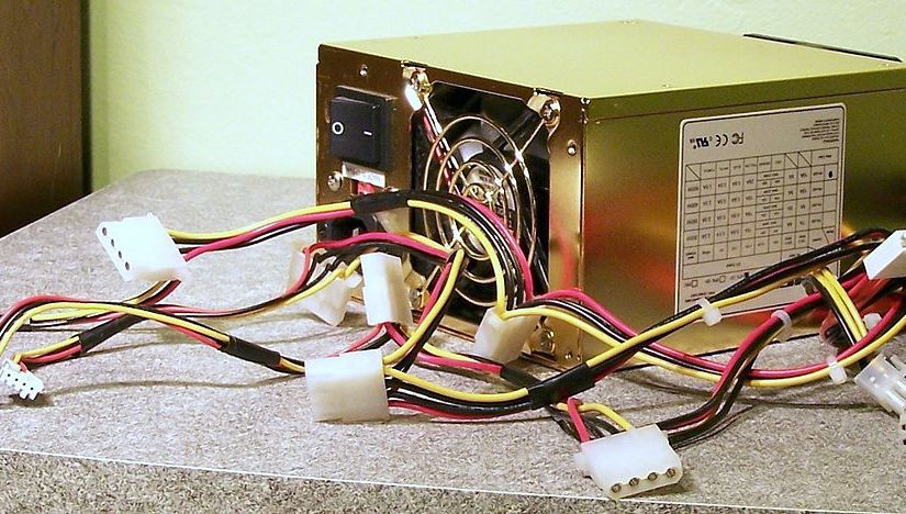
Now, when you first get this PSU, you might want to test it. For that you will need to build a PC yourself. You don’t have one (or all the parts that you need)? Well, you are out of luck. Unless, unless, if you can jumpstart one. This guide will show you how to do so.
UPDATE (9:48 PM EST, 6/30/2021 US Time): I have a new project
I have a new project. I am waiting on its parts. I don’t think I even need to tell you what it is, just look at my stash and you will see:
If you don’t have an adapter that came with your PSU, try these:
1: Grab your 24-Pin motherboard connector:
The 24-Pin Motherboard Connector That Comes With Your PSU
2: Plug your 24-Pin cable into the PSU:
Plug it in
4: There is probably a notch on the power cable. Look for it:
The notch
5. Make the notch turn to your right:
Make it
6. If necessary, make the pins face you:
Make it like this
7. Now the fun, and hard part: Placing the paperclip. Start from the top-right pin, counting down to the bottom-right pin. Once you hit the 4th pin, stick one end of the paperclip. Once you hit the 5th pin, stick the other end. Simply put, in semi-tech terms, short pins 4 and 5 (PS-ON and Ground (GND)):